| [ Overview ] | [ Topics In Depth ] | [ Reference ] | [ Tutorial ] |
Begin by launching Meshwork. An empty model window called "Untitled" should appear. By default, it shows a view of the model from the front (you can tell this by looking at the label in the lower-left corner); the default material is zero (which, by default, is white), and the default tool is the "Add Vertex" tool.
There are two ways to approach an object like this; you can construct it freeform, by hand, or you can assemble it from built-in primitives. A mushroom is basically half a sphere on top of a short cylinder, so let's use the primitives.
From the Create menu, choose the Sphere command. The default settings should be fine, except that I suggest turning on "Stagger" -- this gives a more rounded appearance, without using any more triangles. (See Create Menu for more info.) Click OK, and the sphere will be created as specified, selected and centered on the origin, as shown at right.
Now, we only need the top half of the sphere, not the whole thing. So we want to select the vertices which are entirely within the bottom hemisphere, and delete them. Click on the selection tool ( Now might be a good time to save -- use the File menu as with any standard Mac app, and call it something like "shroom.mesh". (The ".mesh" extension is not necessary, but it is sometimes convenient, so we'll use it here.)
This might also be a good time to explore other camera views -- use the Camera Menu to examine your hemisphere from various sides, or from four angles at once. We'll continue by choosing a Blueprint view (command-7). The result should look like the figure at right, unless you also have 3D glasses, in which case I suggest you don them and turn on the extremely cool Anaglyph mode (command-Y).
Next, we need to make the stem. That's basically a short cylinder, so we'll use the Create menu again, this time choosing the Cylinder command. Recalling that our sphere was 100 units in diameter, let's make the cylinder half that, and reduce the height by half as well. Enter "50" for the diameter and height, and check the Stagger checkbox again, then click OK. A cylinder should appear, centered on the origin.
We're going to be treating the stem and the cap as two different objects for many operations, such as dragging and texturing. So while it's still selected from the creation process, change its material right away. Just click on the second color in the material palette (by default, dark blue). The stem should change to blue, and remain selected. Now, if you want to select the cap again, you can command-click the first material (white) in the palette; and to select the stem, command-click the second material (blue).
The shape and size are pretty good, but the position is wrong; we need the top of the stem to be about the same level as the bottom of the cap. Select it if it's not still selected from the previous step. Then grab any vertex with the mouse cursor, and simply drag it down until it's positioned about right. In fact, drag it down so that the top is a little bit below the bottom of the cap; this will make it a little easier to work with, and we can reposition it later. The result should look something like the figure at right.
Next, let's connect the stem to the cap. This may seem tricky at first, because our three-dimensional model has a lot of points which overlap on a two-dimensional screen, no matter how you look at it. From the top or bottom camera, the top of the cylinder overlaps with the bottom; and from the front or side, the points close to you overlap with points on the opposite side. The solution is to hide the points not involved in whatever you're doing.
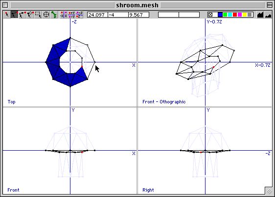
In this case, we only need the vertices at the top of the stem and the base of the cap. Select these points by using the Selection tool, and dragging a box around both sets of points. Then go to the Display Menu, and use the Hide Others command (command-G). All unselected points and edges should be drawn in a light blue, and cannot be selected until they are unhidden. When viewed from the top or bottom, the remaining points do not overlap at all.
You could draw the faces which connect the stem to the cap from either the top view or the bottom view. Since the top view is visible in blueprint mode, let's use that. (This will cause the connecting faces to face up, rather than down as they should, but we can fix that later.)
Deselect all (command-D), then choose the Edge tool ( Now, faces (triangles) in Meshwork are one-sided; i.e., they're visible from one direction but not from the opposite direction. (This is because many game engines have the same feature, known as backface culling, in order to improve rendering speed.) When a new face is created, it is always made to face the camera. Since we created these join faces in the top view, they are facing up, into the cap, and would be invisible from below. To confirm this, turn off blueprint view (command-7), and switch to Bottom view
(command-4). The faces are outlined, but not drawn in blue. Fix this as follows. Do a Select All (command-A), go to the Transform menu, and choose the Face Front command (command-F), while still viewing with the bottom camera. The faces will be filled in, indicating that they now face the bottom as they should.
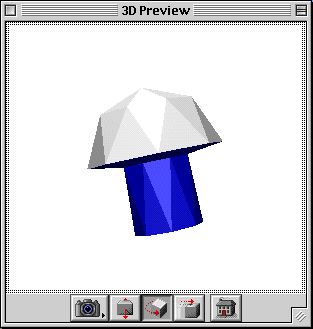
Let's see how our mushroom is coming along. Return to the Blueprint view (command-7), and using the Display menu, unhide all points (command-U). That gives us several views of the mushroom. For an even better feel of the 3D shape, return to the Display menu, and use the 3D Preview command. After a brief pause, a 3D Preview window should appear, as shown at right. (Note: this preview is available only in the PowerPC version of Meshwork, and its quality depends on the version of QD3D installed on your Mac; the QD3D viewer was significantly improved in QD3D 1.6.)
The basic shape is done, but it looks rather artificial -- let's do some shaping. Still using the Selection tool, drag a marquis (selection box) around the very bottom of the mushroom, probably in the Front pane of the blueprint view. From the Transform menu, select the Scale command. Scale it on the X axis by 110%, and on the Z axis by 115%, so it's no longer a perfect circle. Click OK to do the scaling. Then grab any selected (red) vertex in the front view, and drag it up and to the side a bit, to make the stem squatter and less symmetrical.
To make it even more natural-looking, we can manually adjust the positions of several vertices in each "ring" of the mushroom. To do this, select a ring (the bottom ring may be already selected from above), and use the Hide Others (command-G) command. Then, with the selection tool, click anywhere not on the model to deselect all (or use command-D), and click on a single vertex to select it. Then you can simply drag the vertex into position, or use the keyboard controls. Repeat with other vertices. To do the next level, Show All (command-U), and repeat with the next ring of vertices. Scale or transform the ring as a group, or adjust each vertex individually, until you're satisfied with the shape of your mushroom.
To check your progress in 3D, use the 3D Preview command again. This reloads your model into the 3D window. (Note: even if you leave the preview window open, you must use this command to update its data after changing the model.)
Let's make the underside of the cap a different color -- in mine, it's currently blue, because that was the material selected when I joined the cap to the stem. Draw a selection box around both the bottom of the cap, and the top of the stem -- this should include all the triangles in the cap underside, but no others. Then click on the third material (or whatever other material you wish; I like to use them in order, but it's not necessary). Let's go ahead and give it a more appropriate color while we're at it. Double-click the material you just selected, bringing up the material properties dialog. Click on the Color box to summon the standard color picker. I chose a pale yellow. Click OK to dismiss the color picker, then the material dialog.
Now you can select the stem by command-clicking on its material in the material palette. Move it up a bit so that its top is just a little bit above the bottom of the cap (or wherever you think it looks most like a mushroom). Then, use the material dialog to change its color from blue to a light beige. Also, you might want to click the "smooth" checkbox in the material dialog; this will provide the model with vertex normals, resulting in smoother shading.
We're almost done -- we just need to make a texture map for the cap, so we can have a spotted mushroom. First, command-click the first material in the palette to select the cap. Then double-click that same material to bring up its properties dialog. Click on "smooth" to get smoother shading. Then examine the texture-mapping options to the right.
Since I hate to waste texture memory (it's very precious in games), let's use this planar mapping even though it means that the spots around the edge of the cap will be stretched a bit -- we could compensate for that by pre-stretching the texture, or by tweaking the final model with something like Pangea's "3DMF Mapper". Notice that the material dialog has made a texture "sketch" -- that is, it has flattened the material's mesh onto the texture box, giving us a template to work from. Copy this template, which should look something like the figure at left.
Paste the template into your favorite paint program, color it in as you wish, and copy to the clipboard. Or, if you prefer, copy the texture at right, which I threw together using GraphicConverter. Return to Meshwork, and bring up the properties dialog for the cap material again. Paste. Click OK, then save the model. Note that the texture is not drawn in the editing window, but when you do a 3D Preview, the texture is visible.
That's it! The finished result should look something like this (left).
For further exploration:


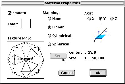 Since the cap is basically a hemisphere, there are two sensible choices for the mapping. One is to use spherical mapping around the Y axis, centered on the origin and with the default extent (100, 100, 100). That would be perfect if we had a whole sphere, but since we have only half of one, this wastes half the texture map. The alternative is to use a planar mapping, also along the Y axis. The default center and extent are pretty good in this case too, but since we have the cap selected, we can customize the positioning by clicking the "Set:" button. The material properties dialog should look something like the figure at right.